Introduction
In the intricate world of industrial fluid control systems, needle valve manifolds stand as critical components that ensure precise flow regulation and system reliability. These sophisticated assemblies combine multiple needle valves into a unified configuration, offering engineers unprecedented control over hydraulic and pneumatic processes across diverse industries.
What Are Needle Valve Manifolds?
A needle valve manifold is an integrated assembly consisting of two or more needle valves mounted on a common block or base. Each valve features a tapered, needle-like stem that fits precisely into a matching seat, enabling fine-tuned flow control through gradual opening and closing mechanisms. The manifold design consolidates multiple control points into a compact, organized unit, reducing installation complexity while enhancing operational efficiency.
The fundamental principle behind needle valve operation relies on the precise relationship between the needle-shaped plunger and the valve seat. As the stem advances or retracts, the annular space between the needle tip and seat changes incrementally, allowing operators to achieve extremely accurate flow rates—from complete shutoff to maximum throughput—with exceptional repeatability.
Key Design Features
Compact Integration
Manifold configurations eliminate the need for individual valve mounting, reducing footprint by up to 60% compared to discrete valve installations. This space-saving advantage proves invaluable in equipment with limited installation areas, such as offshore platforms, aerospace applications, and mobile hydraulic systems.
Multiple Port Configurations
Standard manifold designs accommodate various port arrangements including inline, angle, and parallel configurations. Common setups include 2-valve, 3-valve, and 5-valve manifolds, each serving specific application requirements. The 3-valve manifold, particularly popular in pressure transmitter installations, enables safe isolation, calibration, and venting operations without process interruption.
Material Versatility
Manufacturers produce needle valve manifolds from diverse materials including stainless steel (316SS, 304SS), brass, carbon steel, and specialized alloys like Hastelloy and Monel. Material selection depends on fluid compatibility, operating temperature ranges, pressure ratings, and environmental conditions. Stainless steel variants dominate corrosive environments and high-purity applications, while brass suits general-purpose water and air systems.
Pressure and Temperature Ratings
Modern needle valve manifolds handle working pressures from vacuum conditions up to 10,000 PSI (689 bar) and temperatures ranging from -65°F to 1200°F (-54°C to 649°C). High-pressure variants feature reinforced body construction and enhanced sealing mechanisms to maintain integrity under extreme operating conditions.
Primary Applications
Instrumentation and Process Control
Instrument manifolds represent the most widespread application, connecting pressure transmitters, gauges, and sensors to process lines. The 5-valve manifold configuration enables comprehensive functionality: two block valves isolate the transmitter, one equalizing valve balances pressure during calibration, and two vent/drain valves facilitate maintenance and zero-check procedures. This arrangement ensures accurate measurements while protecting sensitive instrumentation from process shocks.
Hydraulic Systems
Hydraulic needle valve manifolds regulate fluid flow in heavy machinery, injection molding equipment, and industrial presses. Their ability to provide smooth, vibration-free flow control makes them ideal for applications requiring precise actuator positioning and speed regulation. Multi-valve manifolds simplify hydraulic circuit design by consolidating directional control, flow regulation, and pressure relief functions.
Chemical and Petrochemical Processing
Corrosion-resistant manifold assemblies manage aggressive chemicals, acids, and hydrocarbons in refineries and chemical plants. Double-block-and-bleed configurations enhance safety by providing redundant isolation barriers with intermediate venting, preventing hazardous material leakage during maintenance operations.
Oil and Gas Industry
Subsea and topside installations utilize high-pressure manifolds for wellhead control, Christmas tree assemblies, and production monitoring systems. API 6A certified manifolds withstand harsh offshore environments while maintaining reliable performance under cyclic loading and extreme temperature variations.
Pharmaceutical and Biotechnology
High-purity sanitary manifolds with electropolished surfaces and minimal dead legs serve clean-in-place (CIP) and steam-in-place (SIP) systems. These assemblies meet stringent FDA and cGMP requirements, ensuring product integrity in sterile manufacturing environments.
Installation and Maintenance Best Practices
Proper Installation Techniques
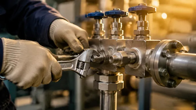
Correct manifold installation begins with verifying orientation arrows align with process flow direction. Apply appropriate thread sealants or gaskets based on connection types—NPT threads require PTFE tape or pipe dope, while flanged connections need properly rated gaskets. Avoid overtightening, which can distort valve bodies and compromise sealing surfaces. Torque specifications typically range from 15-30 ft-lbs for standard sizes, though manufacturer guidelines should always take precedence.
Support manifold weight independently when connecting to sensitive instruments; never allow the instrument to bear the manifold's weight. Use backing wrenches on valve bodies during piping connections to prevent stress transmission to internal components.
Routine Maintenance Protocols
Regular inspection schedules should verify external leakage at all connection points, smooth stem operation, and absence of corrosion or mechanical damage. Lubricate stem threads periodically with compatible lubricants to prevent seizing and ensure precise adjustment capability. For critical applications, establish preventive replacement intervals based on operating cycles and service history.
When disassembling manifolds for maintenance, document original component positions and orientations. Replace worn seats, damaged needles, and degraded seals with genuine manufacturer parts to maintain performance specifications. After reassembly, conduct pressure testing at 1.5 times working pressure to confirm leak-tight integrity before returning to service.
Troubleshooting Common Issues
Flow instability often indicates debris accumulation in valve seats or worn needle tips. Flush the system and inspect internal components if erratic flow patterns emerge. External leakage at stem packing suggests compression ring degradation; tighten the packing nut incrementally or replace packing materials as needed. Stiff stem operation typically results from corrosion, contamination, or misalignment—clean thoroughly and verify proper assembly alignment.
Selection Criteria
Choosing the appropriate needle valve manifold requires evaluating several critical parameters:
•Operating Conditions: Define maximum working pressure, temperature extremes, and flow rates. Select pressure ratings at least 25% above maximum anticipated operating pressure to accommodate transient spikes.
•Fluid Compatibility: Match wetted materials to process media using chemical compatibility charts. Consider factors like pH levels, abrasiveness, and potential for crystallization or polymerization.
•Connection Requirements: Specify end connections compatible with existing piping—common options include NPT, BSP, SAE, VCR, and flanged interfaces. Verify thread standards match regional conventions.
•Certification Standards: Ensure manifolds meet applicable industry certifications such as ASME B31.3, API 6A, ISO 10423, or PED 2014/68/EU for European markets. Fire-safe certifications (API 607/6FA) may be necessary for hydrocarbon service.
•Functional Configuration: Determine the number of valves required based on application needs. Instrument applications typically use 3-valve or 5-valve designs, while simple shutoff duties may only require single or double valve manifolds.
Future Trends and Innovations
The needle valve manifold industry continues evolving with smart instrumentation integration, IoT-enabled monitoring capabilities, and advanced materials science. Manufacturers now offer manifolds with embedded sensors that transmit real-time position feedback, pressure data, and diagnostic information to central control systems. Additive manufacturing techniques enable complex internal geometries that optimize flow characteristics while minimizing pressure drops.
Surface treatment innovations like diamond-like carbon (DLC) coatings enhance wear resistance and reduce friction, extending service life in demanding applications. Modular manifold designs with interchangeable valve cartridges simplify maintenance and reduce downtime, while standardized interface protocols facilitate rapid system reconfiguration.
Conclusion
Needle valve manifolds represent essential components in modern industrial fluid control systems, offering precise regulation, compact design, and reliable performance across diverse applications. Understanding their design principles, application-specific configurations, and proper maintenance practices enables engineers to optimize system efficiency, enhance safety, and minimize operational costs. As industrial processes become increasingly automated and data-driven, intelligent manifold solutions will continue advancing, providing even greater control precision and operational insight for tomorrow's engineering challenges.
Whether managing critical instrumentation signals, regulating hydraulic actuators, or controlling chemical processes, selecting and maintaining the right needle valve manifold ensures optimal system performance and long-term reliability. By adhering to established best practices and staying informed about technological advancements, professionals can maximize the value these versatile components deliver throughout their service life.