In the intricate circulatory systems of modern industry—spanning petrochemical plants, pharmaceutical manufacturing facilities, food processing lines, and precision instrumentation—the integrity of piping connections is paramount. A single compromised joint can lead to catastrophic leaks, severe safety hazards, environmental contamination, and crippling operational downtime. This comprehensive guide delves deep into the technical nuances of ferrule and flanged fittings, offering a comparative analysis designed to empower industry professionals with the knowledge required to make informed, highly optimized selection decisions.
1. Structural Composition: The Anatomy of a Connection
To understand how these fittings perform under extreme conditions, we must first examine their structural DNA. The physical components of a fitting dictate its strength, flexibility, and compatibility with various media.
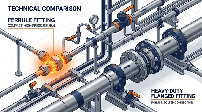
The Precision of Ferrule Fittings
The Fitting Body: The central hub that receives the tube. It features a precision-machined conical seat that guides the ferrules during assembly.
The Nut: The driving force of the connection. As the nut is tightened, it pushes the ferrules forward into the fitting body.
The Front Ferrule: The primary sealing element. It is driven into the conical seat of the body, creating a robust, leak-tight seal against the tube's outer diameter.
The Back Ferrule: The gripping element. It advances axially to grip the tube securely, providing exceptional resistance to vibration and mechanical pull-out, while also translating the torque from the nut into axial thrust against the front ferrule.
The Robustness of Flanged Fittings
The Flanges: Two opposing metallic discs or rings attached to the ends of the pipes (often via welding or threading). They feature raised or flat faces designed to mate with each other.
The Gasket: The sacrificial sealing element placed between the two flange faces. Depending on the media and temperature, gaskets can be made of elastomers, PTFE, graphite, or spiral-wound metals.
Bolts and Nuts: The clamping mechanism. Multiple bolts are distributed evenly around the perimeter of the flanges to compress the gasket uniformly.
2. Sealing Principles: Physics in Action
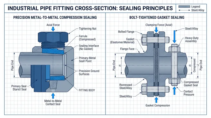
Ferrule Fittings: Plastic Deformation and Swaging
The sealing mechanism of a ferrule fitting relies on controlled mechanical deformation. When the nut is tightened to the manufacturer's specified turns, the back ferrule engages the tube, biting into its surface to create a strong mechanical hold. Simultaneously, it drives the front ferrule into the tapered body seat. This action forces the front ferrule to undergo localized plastic deformation, burnishing against the tube and the fitting body. This creates a continuous, metal-to-metal seal that is highly effective at containing fugitive emissions, even with small-molecule gases like hydrogen or helium.
Flanged Fittings: Compressive Stress and Gasket Yield
Flanged joints achieve a seal through the application of immense compressive force. When the bolts are tightened (torqued) in a specific cross-pattern, they draw the two flange faces together. This action compresses the gasket trapped between them. For a successful seal, the compressive stress exerted by the bolts must exceed the yield strength of the gasket material, forcing it to flow into the microscopic imperfections of the flange faces. Furthermore, this residual clamping force must remain higher than the internal hydrostatic end force exerted by the pressurized fluid trying to push the flanges apart.
3. Installation Methods: Skill vs. Scale
Installing Ferrule Fittings: Agile and Tool-Efficient
Preparation: The tube must be cut square, deburred, and cleaned.
Assembly: The nut and ferrules are slipped over the tube, which is then inserted into the fitting body until it bottoms out on the shoulder.
Tightening: Using standard wrenches, the nut is tightened a specified number of turns (e.g., 1-1/4 turns past finger-tight).
Verification: Installers can use a simple gap inspection gauge to verify that the fitting has been sufficiently tightened, eliminating guesswork and ensuring a safe connection without the need for hot work (welding).
Installing Flanged Fittings: Heavy-Duty Alignment
Attachment: The flanges must first be permanently attached to the pipes, usually requiring skilled welders, hot work permits, and subsequent non-destructive testing (NDT) of the welds.
Alignment: The two piping sections must be perfectly aligned. Misalignment can lead to uneven gasket compression and subsequent leaks.
Torquing: The bolts must be tightened using calibrated torque wrenches or hydraulic tensioners. A strict crisscross torquing sequence is mandatory to ensure uniform compression of the gasket. Failure to follow the sequence can crush the gasket on one side while leaving a leak path on the other.
4. Application Scenarios: Finding the Right Fit
Where Ferrule Fittings Excel
Instrumentation and Analytical Systems: Impulse lines, gas chromatographs, and sampling systems where internal volumes must be minimized and zero-leakage is critical.
High-Pressure Environments: Hydraulic systems and high-pressure gas lines (up to 10,000 psi or more), provided the tubing diameter is relatively small (typically under 2 inches).
Semiconductor and Cleanrooms: Utilizing ultra-high-purity (UHP) ferrule fittings to transport specialty gases without introducing particulate contamination.
Vibration-Prone Areas: The dynamic gripping action of the back ferrule makes these fittings highly resistant to fatigue failure caused by heavy machinery vibration.
Where Flanged Fittings Dominate
Large Diameter Piping: Any application requiring pipe sizes above 2 inches (and up to several feet in diameter), such as main cooling water lines, oil pipelines, and bulk chemical transfer.
High Flow Rates: Petrochemical refineries and power generation plants where massive volumes of liquid or steam must be moved efficiently.
Equipment Connections: Flanges are the standard interface for connecting pipes to large equipment like pumps, compressors, heat exchangers, and massive storage tanks, allowing for relatively easy bolting and unbolting during major overhauls.
5. Cost-Effectiveness: Beyond the Initial Purchase
Initial Material Costs: For small diameters (under 1 inch), ferrule fittings are often more cost-effective as they eliminate the need for bulky flanges, multiple bolts, and gaskets. As diameters increase, the high-precision machining required for large ferrule fittings makes them prohibitively expensive, making flanges the economical choice.
Installation Labor: Ferrule fittings drastically reduce labor costs. They require no welding, no hot work permits, and no complex X-ray inspections of welds. A trained technician can assemble a ferrule fitting in minutes. Flanges require skilled welders, heavy lifting equipment for large sizes, and meticulous torquing procedures.
Maintenance and Lifecycle: Flanged joints require periodic maintenance. Gaskets degrade over time due to thermal cycling and chemical attack, and bolts can experience relaxation, requiring re-torquing. Ferrule fittings, once properly installed, generally offer a "fit-and-forget" solution with excellent long-term reliability. However, if a flanged section needs to be completely replaced, it is easier to unbolt a spool piece than to cut and replace rigid tubing lines.
Conclusion & Selection Guide
The debate between ferrule fittings and flanged fittings is not a matter of one being inherently superior to the other; rather, it is a question of engineering appropriateness.
Select Ferrule Fittings when:
Working with tubing diameters generally under 2 inches.
Handling hazardous, toxic, or highly penetrative gases where zero-leakage is non-negotiable.
Operating in confined spaces where welding is impossible or unsafe.
The system experiences high vibration or rapid thermal cycling.
Rapid installation and immediate system start-up are required.
Select Flanged Fittings when:
Designing main process lines with large diameters and high flow capacities.
Connecting piping to major industrial equipment (pumps, vessels, reactors).
The system requires frequent disassembly of large spool pieces for internal cleaning or inspection.
Working with heavy-walled pipes rather than thin-walled tubing.
Ultimately, the integrity of an industrial facility relies on a hybrid approach. By understanding the structural anatomy, sealing physics, and lifecycle costs of both methods, procurement and engineering teams can design piping networks that maximize safety, optimize performance, and drive long-term operational excellence.


