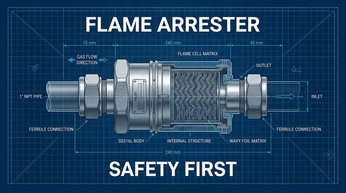
In modern industrial landscapes—ranging from petrochemical refineries and pharmaceutical manufacturing to advanced specialty gas delivery systems—the margin for error is virtually nonexistent. Among the most critical safety components guarding against catastrophic failures are flame arresters. Specifically, for small-bore instrumentation and gas distribution pipelines, the Ferrule Flame Arrester (often referred to as the Card Type Flame Arrester) stands as the ultimate line of defense. This comprehensive technical guide explores the intricate engineering behind ferrule flame arresters, providing an in-depth analysis of their operational principles, structural types, stringent selection criteria, and professional installation guidelines. Whether you are a process engineer, a safety compliance officer, or a pipeline designer, understanding the nuances of these devices is paramount to ensuring the integrity of your hazardous material handling systems.
1. The Core Physics: How Ferrule Flame Arresters Extinguish Flames
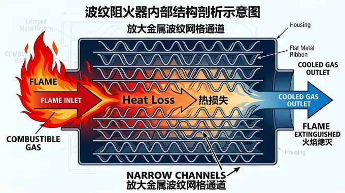
At its fundamental level, a flame arrester is a passive mechanical device designed to allow the flow of gases or liquids while preventing the transmission of a flame. The operating principle of the card type flame arrester is grounded in thermodynamics and fluid mechanics.
"The card type flame arrester extinguishes flames via heat loss through narrow pores of thermal conductors."
When an ignition occurs and a flame front travels down a pipeline, it eventually encounters the flame arrester element (often referred to as the matrix or core). This element consists of intricately designed micro-channels. As the flame attempts to pass through these narrow passages, the highly conductive metallic structure absorbs the heat from the combustion process. This rapid thermal dissipation lowers the temperature of the reacting gas mixture below its auto-ignition temperature, effectively quenching the flame and preventing the explosion from propagating further down the line.

2. Structural Classifications and Types
Ferrule flame arresters are highly versatile, primarily due to the diverse engineering of their internal quenching elements. Depending on the application, the internal matrix can be manufactured in several distinct configurations.
2.1 Classification by Flame Arrester Element Structure
The efficiency of thermal dissipation relies heavily on the internal structure of the arrester. The three primary element types include:
Crimped Ribbon / Corrugated Type: This is widely regarded as the industry standard for high-performance applications. It utilizes tightly wound layers of flat and corrugated metal ribbons (commonly constructed from robust materials like 316L stainless steel or copper-nickel alloys) to form precise, uniform triangular or semi-circular channels. The crimped structure offers an optimal balance between maximum heat dissipation surface area and minimal pressure drop across the device.
Wire Mesh Type: This type employs layers of densely woven metallic wire mesh compacted together. While it is highly effective for certain clean gas applications, it is generally better suited for lower-pressure scenarios. It is favored in compact card-type (ferrule) arresters designed for small pipelines (e.g., 1/4" to 1" diameters).
Gravel Type (316 Material): Utilizing densely packed metallic gravel or sintered 316 stainless steel granules, this structure creates a randomized, highly tortuous path for the gas. It is incredibly robust and highly resistant to mechanical shock, making it suitable for high-stress environments, though it may introduce a higher pressure drop compared to the crimped ribbon design.
2.2 Classification by Combustion Condition
Understanding the nature of the potential explosion is vital. Flames in a confined pipeline accelerate, and their behavior changes drastically as they travel.
Deflagration Flame Arresters: Designed to stop subsonic flames (flames traveling slower than the speed of sound). These are typically used when the arrester is installed close to the potential ignition source, before the flame has the runway to accelerate significantly.
Detonation Flame Arresters: Designed to withstand and extinguish supersonic flames and the accompanying high-pressure shock waves. If a pipeline run is long, a deflagration can transition into a detonation. Arresters rated for detonation require substantially heavier housings and highly reinforced core structures to survive the extreme kinetic and thermal energy.
3. Engineering the Perfect Fit: Selection Criteria
Specifying the correct ferrule flame arrester is not a matter of guesswork; it requires a rigorous assessment of process parameters and adherence to international standards such as NFPA 69 (Standard on Explosion Prevention Systems) and IEC 60079-20-1 (Material characteristics for gas and vapour classification).
3.1 Analyzing the Gas and Medium Properties
Maximum Experimental Safe Gap (MESG): This metric defines the maximum clearance between two parallel metal surfaces that has been found, under specified test conditions, to prevent an explosion in a test chamber from being propagated to a secondary chamber containing the same gas mixture. You must match the arrester’s internal channel gap (mesh or ribbon gap) to be smaller than the MESG of the specific gas.
Minimum Igniting Current Ratio (MICR): Often used in tandem with MESG to classify hazardous gases into groups (e.g., Group IIA, IIB, IIC). Gases like hydrogen (Group IIC) have very small MESG values, necessitating an arrester element with microscopically tight crimped channels.
3.2 Operating Parameters: Pressure, Temperature, and Flow
The mechanical integrity of the arrester housing must align with your system limits:
| Parameter | Typical Specification |
|---|---|
System Pressure | PN16 (or higher) |
Operating Temperature | -20°C to 150°C |
Line Size | 1/4 inch to 1 inch O.D. |
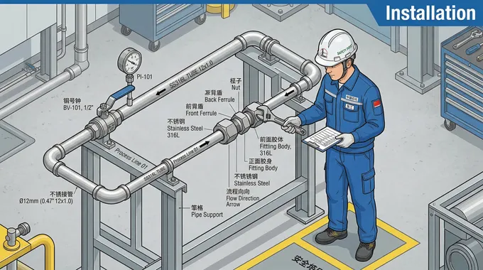
4. Installation Guidelines and Best Practices
The most perfectly engineered flame arrester is rendered useless if improperly installed. The ferrule (or compression fitting) connection mechanism is celebrated for its ease of use, but it demands strict adherence to procedural guidelines.
4.1 The Ferrule Connection Mechanism
Card-type joints are directly screwed onto both ends of the flame arrester. This twin-ferrule or single-ferrule mechanism grips the instrument tubing tightly, creating a robust, leak-tight seal without the need for threading the pipe or welding.
Preparation: Ensure the tubing is cut perfectly square and is free of burrs or scratches.
Tightening: Follow the manufacturer's exact specifications for the number of turns past finger-tight (typically 1-1/4 turns for standard stainless steel fittings). Over-tightening can crush the tubing, while under-tightening compromises the explosion-proof seal.

4.2 Orientation and Positioning
Bi-directional vs. Uni-directional: Determine if the arrester is bi-directional (stops flames from both directions) or uni-directional. Crucial Rule: The flow direction marker (usually an engraved arrow on the housing) must perfectly align with the intended process medium flow.
Physical Orientation: Most highly engineered crimped or gravel-type ferrule arresters can be installed either horizontally or vertically without compromising performance, provided the pipeline is structurally supported to bear the weight of the device.
Proximity to Ignition Source: For inline deflagration arresters, the distance from the potential ignition source to the arrester (the L/D or Length-to-Diameter ratio) must not exceed the certified testing limits, preventing the flame from accelerating into a detonation.
5. Maintenance, Inspection, and System Longevity
A ferrule flame arrester is an active participant in an industrial environment, subject to particulate fouling, chemical attack, and moisture accumulation. Standard maintenance protocols are non-negotiable.
Routine Inspection: Regularly inspect the device for external corrosion or mechanical damage.
Internal Diagnostics: The narrow pores of the thermal conductors (the crimped ribbons or wire meshes) are susceptible to blockages from process impurities. A blocked arrester increases pressure drop and restricts flow. Periodically monitor the differential pressure across the arrester; a sudden spike indicates a fouled element.
Cleaning and Replacement: Ensure the crimped element remains intact. If the element is removed for ultrasonic cleaning, it must be handled with extreme care. Any mechanical deformation of the micro-channels instantly voids its flame-quenching capability. If the element is corroded or irreversibly clogged, it must be replaced with OEM-certified components.
Conclusion
The deployment of Ferrule (Card Type) Flame Arresters is a critical engineering decision that bridges the gap between operational efficiency and catastrophic risk mitigation. By understanding the thermodynamic principles of heat loss through narrow pores, correctly interpreting metrics like MESG, and adhering to strict installation protocols utilizing secure card-type joints, facilities can ensure robust protection against both deflagrations and detonations. In the realm of hazardous gas handling, safety is not merely a regulatory checkbox—it is a continuous commitment to precision engineering. By selecting the right arrester, respecting the operating parameters (-20°C to 150°C, PN16, 1/4"-1" sizing), and implementing rigorous maintenance routines, industries can safeguard their infrastructure, protect human lives, and maintain uninterrupted operational excellence. Always consult with certified safety engineers and reference definitive standards like IEC 60079-20-1 and NFPA 69 when finalizing your pipeline safety architecture.


