
In the complex world of industrial engineering, piping design, and fluid dynamics, the gap between a schematic drawing and the physical reality on the factory floor can often seem like a canyon. For young engineers, seasoned technicians, and procurement specialists alike, the ability to instantly translate a geometric symbol on a Piping and Instrumentation Diagram (P&ID) into a heavy, cold steel component is a superpower.
This article is not just a glossary; it is a bridge. We will dissect the most common valve types, exploring the logic behind their international symbols (ISO/ISA standards), their physical anatomy, and the critical applications in the real world. Whether you are dealing with ASME B16.34 compliant designs or interpreting GB/T 6567.4 diagrams, this guide is your definitive reference.
Part 1: The Language of Lines – Understanding Standardization
Before diving into specific valves, we must understand the grammar of this visual language. Valve symbols are not arbitrary doodles; they are simplified representations of function, not just form.
According to ISO 10628 and ISA-5.1, a symbol tells you three things:
The Body Style: How the fluid enters and exits.
The Actuation Method: How the valve is operated (manual, pneumatic, electric).
The Flow State: Is it normally open, normally closed, or throttling?
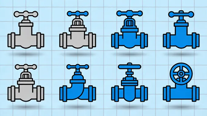
The "Bowtie" symbol—two triangles touching at their vertices—is the universal base. It represents the continuity of the pipe being interrupted by a control mechanism. But the nuances lie in the modifications to this bowtie.
Part 2: Isolation Valves – The Gatekeepers
Isolation valves (or Shut-off valves) are designed to stop or allow flow fully. They are the "On/Off" switches of the piping world.
1. Gate Valve (GV)
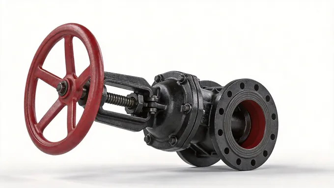
The Symbol Logic: In most P&ID standards, the Gate Valve is represented by the standard "bowtie" symbol, sometimes with a vertical line intersecting the center to represent the "gate" blocking the path.
Physical Reality: When you see a Gate Valve in the field, look for a tall bonnet (the top part). The key feature is the multi-turn handwheel. It functions like a guillotine—a threaded stem lifts a rectangular or circular gate (wedge) out of the fluid path.
Application: Ideal for slurry or thick fluids because the gate cuts through the medium. However, it is terrible for throttling (regulating flow) because the high velocity of partially opened fluid will erode the gate—a phenomenon known as "wire drawing."
Key Takeaway: Low pressure drop when fully open, but slow to operate. Best for infrequent on/off service.
2. Ball Valve (BS/BV)
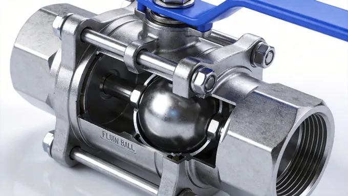
The Symbol Logic: The symbol often features a circle (representing the ball) in the center of the bowtie lines.
Physical Reality: Look for a lever handle rather than a wheel. The handle position indicates the valve state: parallel to the pipe means "Open," perpendicular means "Closed." Inside, a spherical ball with a hole (bore) rotates 90 degrees.
Application: The workhorse of the industry. Excellent for quick shut-off (quarter-turn operation). Widely used in water treatment, gas lines, and chemical processing due to its tight sealing.
Key Takeaway: Excellent for quick shut-off. Terminology to know: "Full Bore" vs. "Reduced Bore."
3. Butterfly Valve (BV)

The Symbol Logic: The symbol typically shows a dot in the center of the bowtie, sometimes with a slanted line indicating the disc. ISO standards may use a specific single-line diagram with a diagonal stroke.
Physical Reality: Compact and thin. This is a "wafer" style valve that fits snugly between two pipe flanges. A disc rotates on a central shaft, functioning like a damper in an HVAC duct.
Application: The king of large diameter pipes (water mains, HVAC cooling towers). It is lightweight and cheap compared to a massive gate valve. However, the disc is always in the flow path, creating a slight pressure drop even when fully open.
Key Takeaway: Lightweight and cost-effective for large diameters, but creates a slight pressure drop.
Part 3: Regulation & Protection – Conductors & Guardians
While isolation valves are simple switches, regulation valves control the amount of flow, and protection valves operate automatically to safeguard the system.
4. Globe Valve (GLV)
The Symbol Logic: Often depicted with a solid dark circle in the center of the bowtie. The darkness implies a heavy, convoluted flow path.
Physical Reality: Physically bulbous body (globular). Like the gate valve, it uses a handwheel, but the body is usually wider. The fluid must flow up, over a seat, and down (an S-shaped path).
Application: The best choice for throttling. Used extensively in steam systems and precise flow regulation. The trade-off is a high pressure drop due to the tortuous path the fluid must take.
5. Needle Valve
The Symbol Logic: Similar to a globe valve but often with an arrow indicating precise adjustment.
Physical Reality: Small, slender, often found on instrumentation lines. A long, tapered needle-like plunger fits into a seat.
Key Takeaway: Extreme precision. Ideal for dampening signals to pressure gauges.
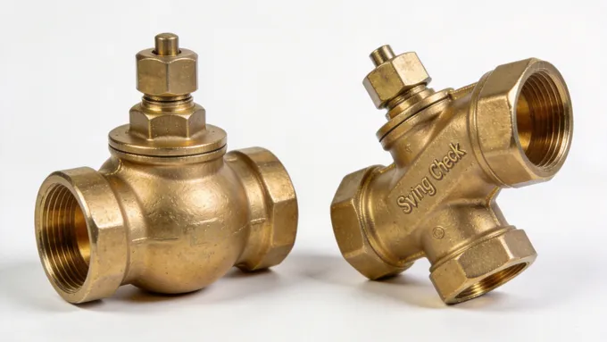
6. Check Valve (CV/NRV)
The Symbol Logic: An arrow inside a circle, or a diagonal line across the pipe line symbol, indicating flow direction. It visually says "One Way Only."
Physical Reality: Often lacks a handle or wheel entirely. It looks like a bulge in the pipe. A flap swings open with forward flow and slams shut with reverse flow (Swing Check).
Key Takeaway: Critical for Pump Protection. Prevents backflow from damaging motors.
7. Safety Relief Valve (SRV)
The Symbol Logic: A right-angle pattern with a spring symbol on top. It signifies a path that opens only when pushed against a force.
Physical Reality: Distinguishable by the large spring housing (bonnet) on top and a side discharge port.
Application: Critical Safety. Found on boilers and pressure vessels. It is the last line of defense against explosions.
Part 5: Specialty Valves & Nameplates
8. Diaphragm Valve
The Symbol Logic: A bowtie with a semi-circle arching over the center, representing the flexible diaphragm.
Physical Reality: Often looks like a "humpback" on the pipe. A flexible membrane is pushed down to seal the flow, meaning the fluid never touches the metal moving parts.
Key Takeaway: Standard for Hygienic/Sanitary use (Pharmaceuticals and Food). No dead spaces for bacteria.
Decoding the Nameplate
When you encounter a valve in the real world, the symbol isn't stamped on it. You read the nameplate. According to JB/T 106-2024 and ASME B16.34, a standard nameplate includes:
DN (Nominal Diameter): The size of the internal bore.
PN (Nominal Pressure) / Class: How much pressure the body can withstand.
Body Material: WCB (Carbon Steel), CF8M (Stainless Steel 316), CI (Cast Iron).
Heat Number: Trace code linking the metal to the foundry batch.
Bridging the Gap
Mastering the correlation between symbols and physical valves is not an academic exercise; it is a fundamental skill for safety and efficiency. For the designer, it prevents spatial conflicts. For the operator, recognizing a symbol can save critical seconds in an emergency.
The valve is the unsung hero of the industrial world. Keep this guide bookmarked. The next time you walk the plant floor or review a complex P&ID, you’ll see not just lines and metal, but a logical, functional system working in harmony.


