
In the complex and high-stakes arena of industrial engineering, ferrule safety valves stand as the ultimate line of defense.
These critical safety protection devices are the silent guardians of pressure vessels, pipelines, and complex fluid systems. Their performance does not merely influence operational efficiency; it directly dictates the safety, stability, and survival of the entire system architecture. When pressures surge beyond design limits, a meticulously calibrated safety valve is the difference between a controlled release and a catastrophic failure. For engineers and maintenance professionals, understanding the nuances of safety valve calibration is non-negotiable. This in-depth technical article systematically unpacks the methodologies, stringent standards, and critical precautions involved in the calibration and testing of ferrule safety valves.
1. The Crucial First Step: Rigorous Preparation Before Calibration
Calibration is a science of precision. The accuracy of the final result is entirely dependent on the quality of the preparatory steps. Establishing a flawless testing environment and utilizing the correct apparatus are foundational to the entire process.
1.1 Precision Equipment and Tooling
The calibration bench must be equipped with instrumentation that strictly adheres to national metrological standards.
• Pressure Source: Engineers must utilize robust hydraulic or pneumatic devices capable of delivering a stable pressure range that covers at least 1.1 times the target set pressure of the safety valve.
• Pressure Gauge: Precision is paramount. The gauge must possess an accuracy class no lower than 0.4, with a total range spanning 1.5 to 2 times the valve's set pressure.
• Thermometer: Continuous monitoring of the media temperature is required to ensure dynamic test conditions mirror operational realities.
• Specialized Fixtures: Utilizing hydraulic three-jaw chucks is standard practice. These must be verified for uniform clamping force (e.g., no-load operation of a 50-ton clamping force for more than three cycles) to guarantee the valve will not loosen.
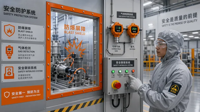
• Protective Gear: High-pressure testing is inherently hazardous. Operators must be equipped with anti-static clothing, industrial-grade safety goggles, and pressure-resistant gloves. All high-pressure tests must be executed behind a reinforced blast shield.
1.2 Media Selection & 1.3 Environmental Control
• Liquid Media: Clean water (deionized or distilled) is the standard. For specialized liquids, simulate the actual media's viscosity.
• Gas Media: Air or nitrogen must be exceptionally dry and entirely oil-free (oil mist < 0.1 mg/m³, dew point 10°C lower than ambient).
• Temperature & Humidity: Ambient and media temperatures must remain stable within a 5-40°C window. Relative humidity must be capped at 85%.
• Safety Layout: A strict 2-meter exclusion zone, free of clutter, must be maintained around the test bench.
2. Decoding the Calibration Process: Key Steps for Precision
The actual calibration process is a methodical sequence of inspection, adjustment, and verification. Each step must be executed with surgical precision.
Step 1: Initial Inspection and Strategic Disassembly
Meticulously clean all impurities from the valve body. Inspect the valve disc and seat sealing surfaces. Utilizing calibrated precision calipers, measure the diameter of the valve disc sealing surface and the valve seat orifice. Use a specialized spring tester to verify its exact elastic coefficient.
Step 2: Pressure Testing and Set Pressure Optimization
Increase the pressure at a controlled rate of 0.1 MPa/min until 90% of the anticipated set pressure. Beyond this, reduce rate to ≤0.01 MPa/s. Record the set pressure as the maximum value when the valve disc audibly opens. Adjust the bolt as needed, performing 1 to 2 actuations to verify.
Step 3: Reseating Pressure and Sealing Integrity Validation
Observe the valve's ability to reseat promptly when pressure drops to ~90% of set pressure. For sealing, maintain target pressure for 5 minutes (Static Test: decay rate ≤0.1 MPa/min; Bubble Method: ≤20 bubbles/min; Pressure Drop Method: ≤5% drop).
Step 4: Pushing the Limits: Extreme Temperature Testing (Optional)
For extreme environments, perform high-temperature tests (preheat to design temp, limit fluctuations to ±5°C) or low-temperature tests (pre-cool below -40°C for 30 mins). Utilize high-temperature rated gaskets and tighten bolting in calculated stages.
3. Navigating Testing Standards and Compliance Protocols
Adherence to established engineering standards is what separates a certified safety device from a dangerous liability.
[GB/T 12242] Dictates rigorous performance test methods for safety valves, laying out exact parameters for set pressure, reseating pressure, and sealing criteria.
[GB/T 12243] Clarifies technical requirements for spring-loaded direct-acting safety valves, mandating that spring fatigue life must exceed 10,000 operational cycles.
[ASME PTC 25.3] Requires that the testing facility possesses sufficient volumetric discharge capacity to guarantee that the relief valve's set pressure error remains within the allowable range.
4. Troubleshooting: Diagnosing and Resolving Common Anomalies
Even with perfect preparation, valves can fail testing. Engineers must possess the diagnostic acumen to identify and rectify these failures swiftly.
Excessive Opening Pressure Deviation
Cause: Severe spring fatigue, valve disc sticking within the guide, or accumulation of media impurities.
Solution: Replace the fatigued spring, thoroughly clean the valve chamber with industrial solvents, and precision-grind the sealing surfaces.
Eradicating Sealing Leakage
Cause: Physically damaged sealing surfaces, insufficient spring preload, or aggressive media corrosion.
Solution: Replace valve disc/seat, recalibrate spring preload, or upgrade to highly corrosion-resistant alloys.
Correcting Low Reseating Pressure
Cause: Insufficient spring stiffness or excessively worn clearance gap between valve disc and guiding sleeve.
Solution: Upgrade to a higher stiffness spring or machine and repair the guide sleeve mating surfaces.
5. Non-Negotiable Safety Protection and Emergency Readiness
Testing ferrule safety valves involves manipulating immense potential energy. Safety protocols must be absolute, redundant, and unforgiving.
Advanced Safeguards & Personnel Protection
• Interlock Systems: Integrate pressure-displacement dual-signal automated interlocks to instantly cut power if clamping force drops or pressure exceeds limits by 10%.
• Remote Execution: High-pressure testing must be executed via remote control from behind a certified blast shield.
• Emergency Response: The test bench must feature an integrated emergency pressure relief valve (response <0.5s, diameter ≥ DN25). Maintain a leak-proof plugging tool kit on standby.
The calibration and testing of ferrule safety valves are not mere bureaucratic checkboxes; they are highly technical, rigorously standardized engineering imperatives. By strictly adhering to national and international metrological standards, intelligently selecting testing media, and executing flawlessly controlled testing procedures, engineers can validate the integrity of these vital components. Through scientifically standardized process control, meticulous data recording, and uncompromising safety protection measures, we ensure that ferrule safety valves will operate flawlessly at the critical moment of system overpressure. Ultimately, this rigorous dedication to testing protocols provides the solid, unwavering guarantee required for the safe, continuous operation of modern industrial equipment.


