In the complex arterial networks of modern industry, valves are the heart valves of the system. However, their reliability is often taken for granted until failure occurs.
Critical Insight: External leakage accounts for approximately 65% of incidents, posing direct environmental and safety risks, while internal leakage (35%) acts as a silent parasite, potentially draining 8% to 15% of a system's total energy efficiency.
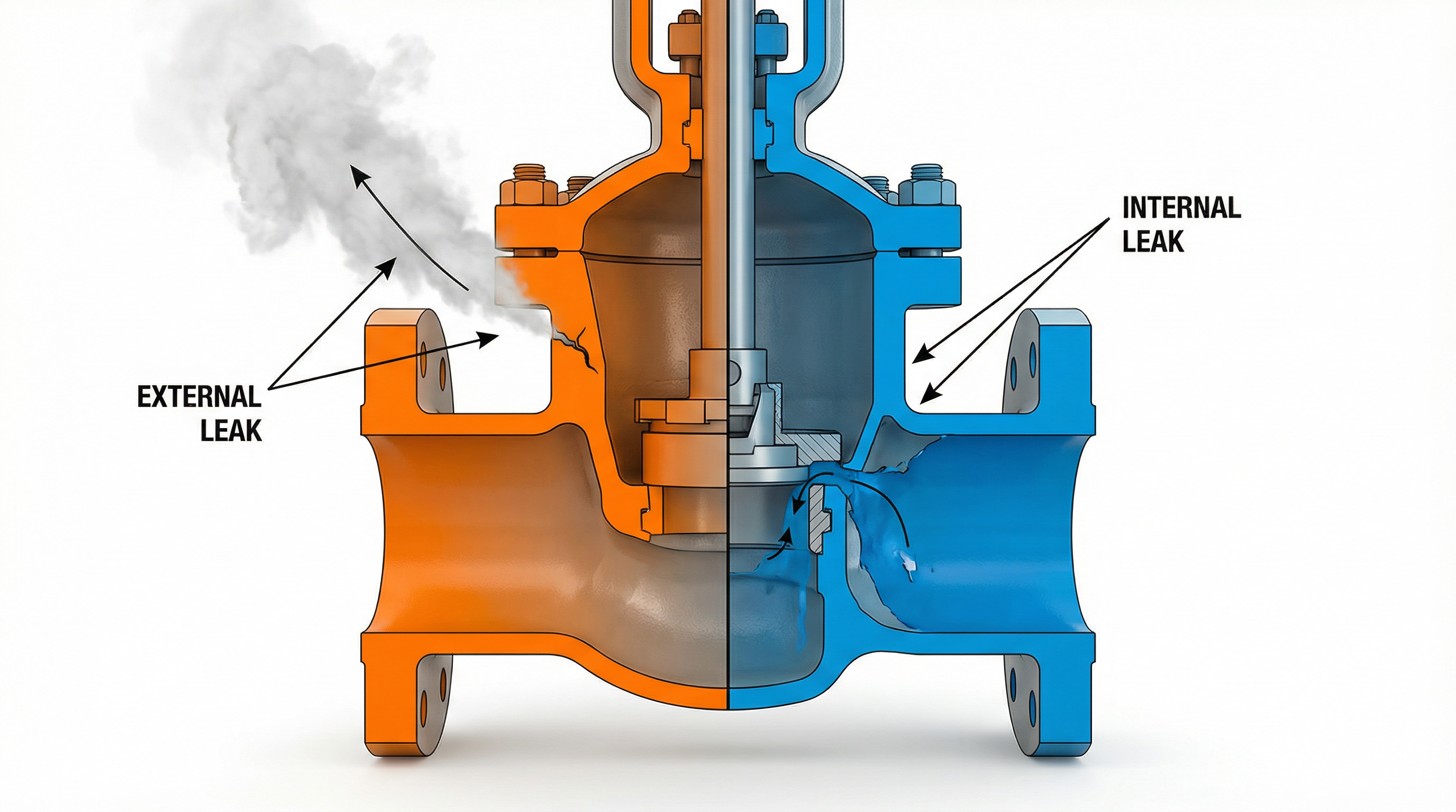
I. External Leakage: The Evolution from Seepage to Environmental Disaster
External leakage is defined as the escape of the process medium from the valve’s pressure boundary—specifically through non-flow paths such as the packing box, flange connections, or defects in the casting body—into the external environment.
1. The "Three-Stage" Hazard Progression
Stage 1: Resource Hemorrhage. The primary impact is economic. For instance, a single steam valve leak can waste tons of medium annually.
Stage 2: Structural Compromise. Acidic or corrosive media leaks accelerate the deterioration of surrounding metal structures.
Stage 3: Catastrophic Event. In volatile industries like hydrogen energy, a minor leak can form an explosive mixture.
2. The Core Causality Matrix
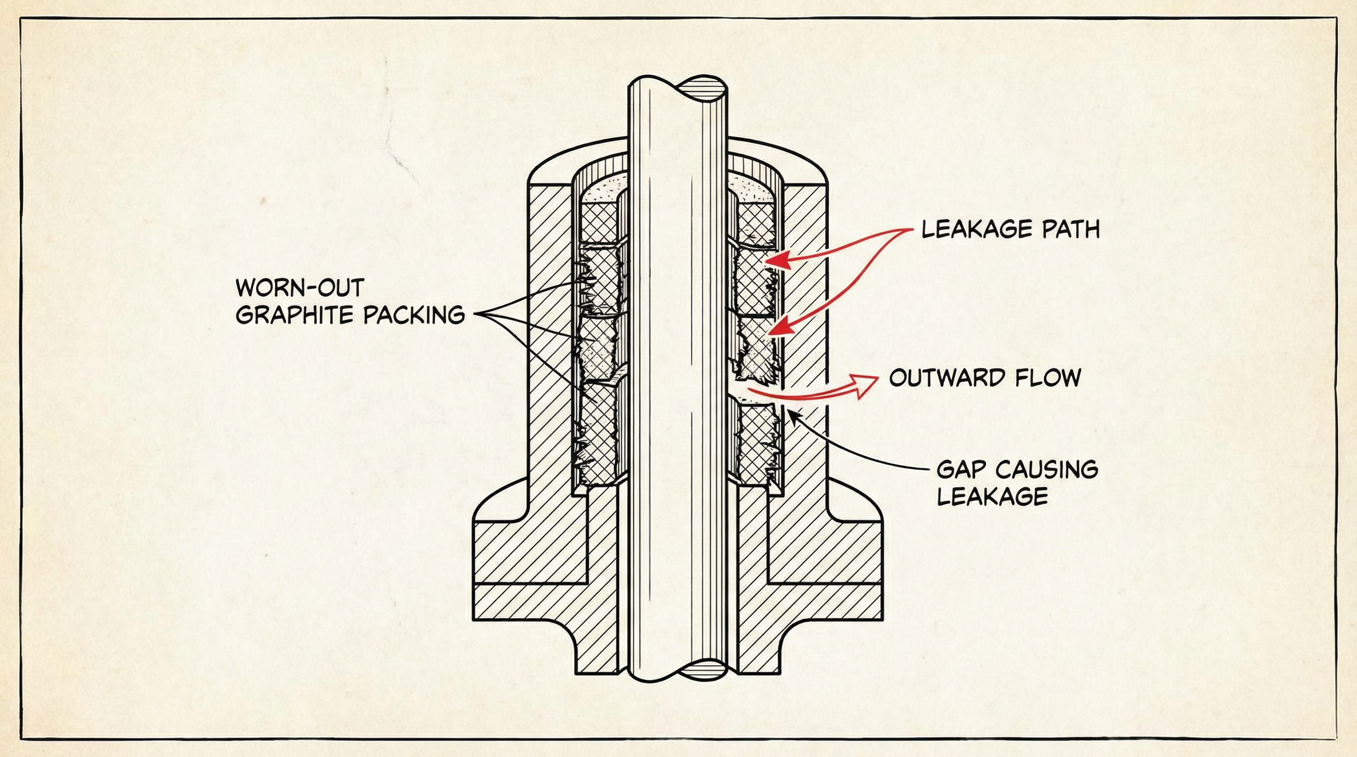
A. Packing System Failure (42% of Incidents): The stuffing box is the Achilles' heel. Graphite packing oxidizes above 450°C, losing volume. Installation errors exceeding ±15% winding angle deviation can skyrocket leakage by 300%. Dynamic wear reaches 0.03-0.05mm per 10,000 cycles.
B. Flange Connection Failure (28% of Incidents): Stress relaxation in bolts (e.g., 304 SS at 350°C) can cause 40% preload loss. Misapplying PTFE gaskets in oxidizing environments leads to rapid failure, while flange face roughness Ra > 6.3μm increases risk fivefold.
C. Structural/Body Defects (19% of Incidents): Casting voids and sand holes in standard cast steel bodies create hidden pathways. Stress concentration zones propagate fatigue cracks at rates up to 0.01mm per cycle.
D. Operational Malpractice (11% of Incidents): Torque overload (e.g., >800N·m on DN200) deforms stem threads. Lack of lubrication raises friction coefficients, accelerating wear by a factor of 10.
3. The Evolution of Detection Technology
Soap Water Cheap but slow (5 min). Limited sensitivity. | Ultrasonic Fast (2s). Detects high-freq gas sound. | Laser Telemetry Instant (0.1s). Remote detection for safety. |
II. Internal Leakage: The Chain Reaction of System Collapse
While microscopic leakage is sometimes tolerated, significant "passing" (>5% rated flow) is devastating: dropping boiler feedwater temps by 15°C and reducing compressor efficiency by 8%.
Mechanisms of Internal Failure
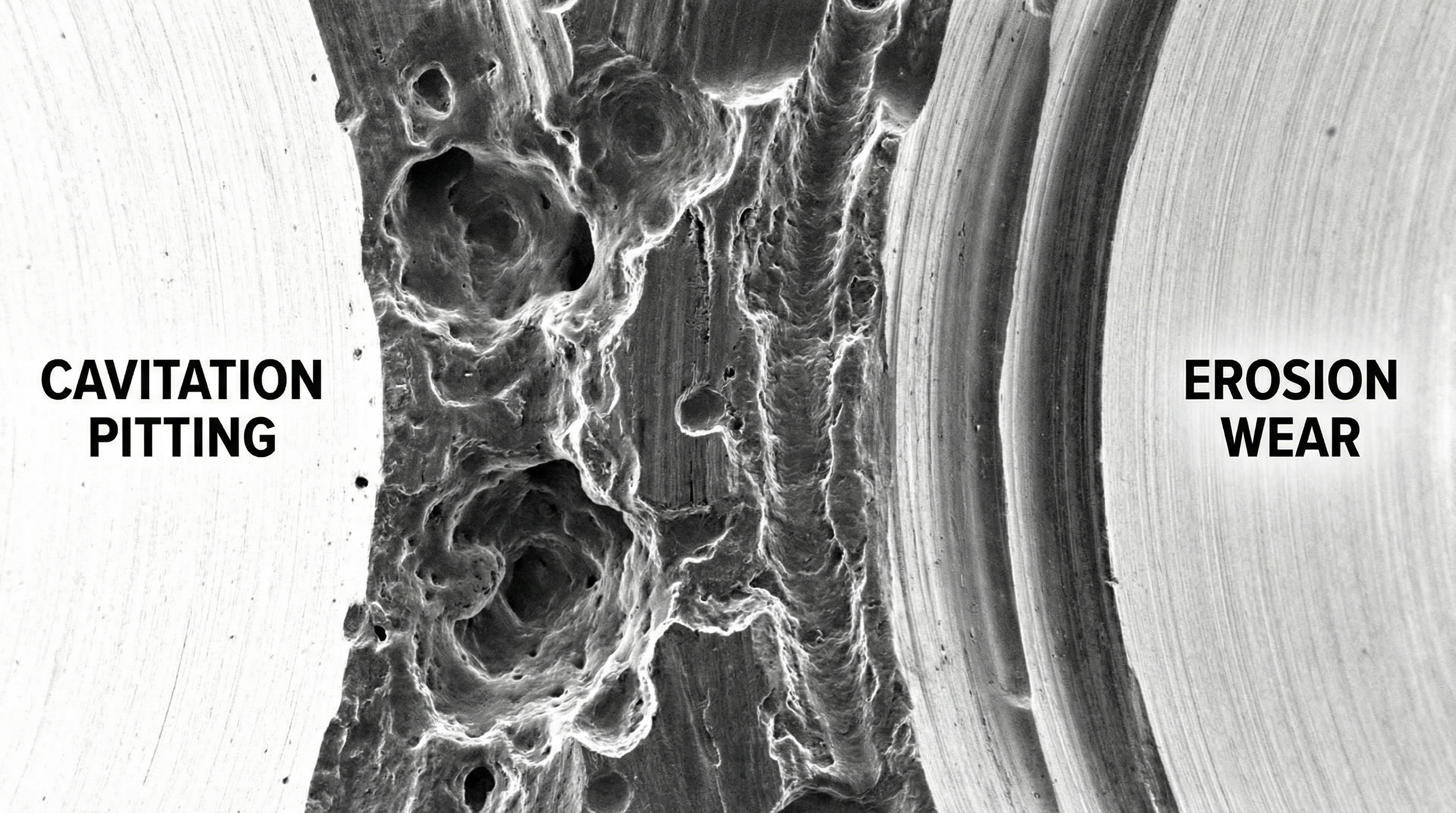
A. Surface Damage Mechanisms: The sealing surface is the battlefield. Erosion occurs when solid particles impact at 15m/s. Cavitation creates micro-jets with impact pressures up to 140 MPa, severely pitting the metal when liquid pressure drops below vapor pressure.
B. Mechanical System Failure: Stem bending (curvature >0.5mm/m) creates direct leak paths. A "hanging" disc, where clearance exceeds 0.2mm, drops sealing force by 40%.
C. Medium-Induced Failure: Phase changes (steam to water) create vacuum effects sucking debris into the seal. Crystallization of media like urea jams the core.
D. Manufacturing Tolerances: Misalignment of seat and disc by >0.1mm increases leakage rates tenfold. Material mismatch (e.g., 304 SS for Hydrogen) risks embrittlement.
III. Constructing a Defense-in-Depth Strategy
Phase I: Design & Engineering |
Phase II: Advanced Manufacturing |
Phase III: Intelligent O&M |
IV. Future Horizons: The Path to Zero Leakage
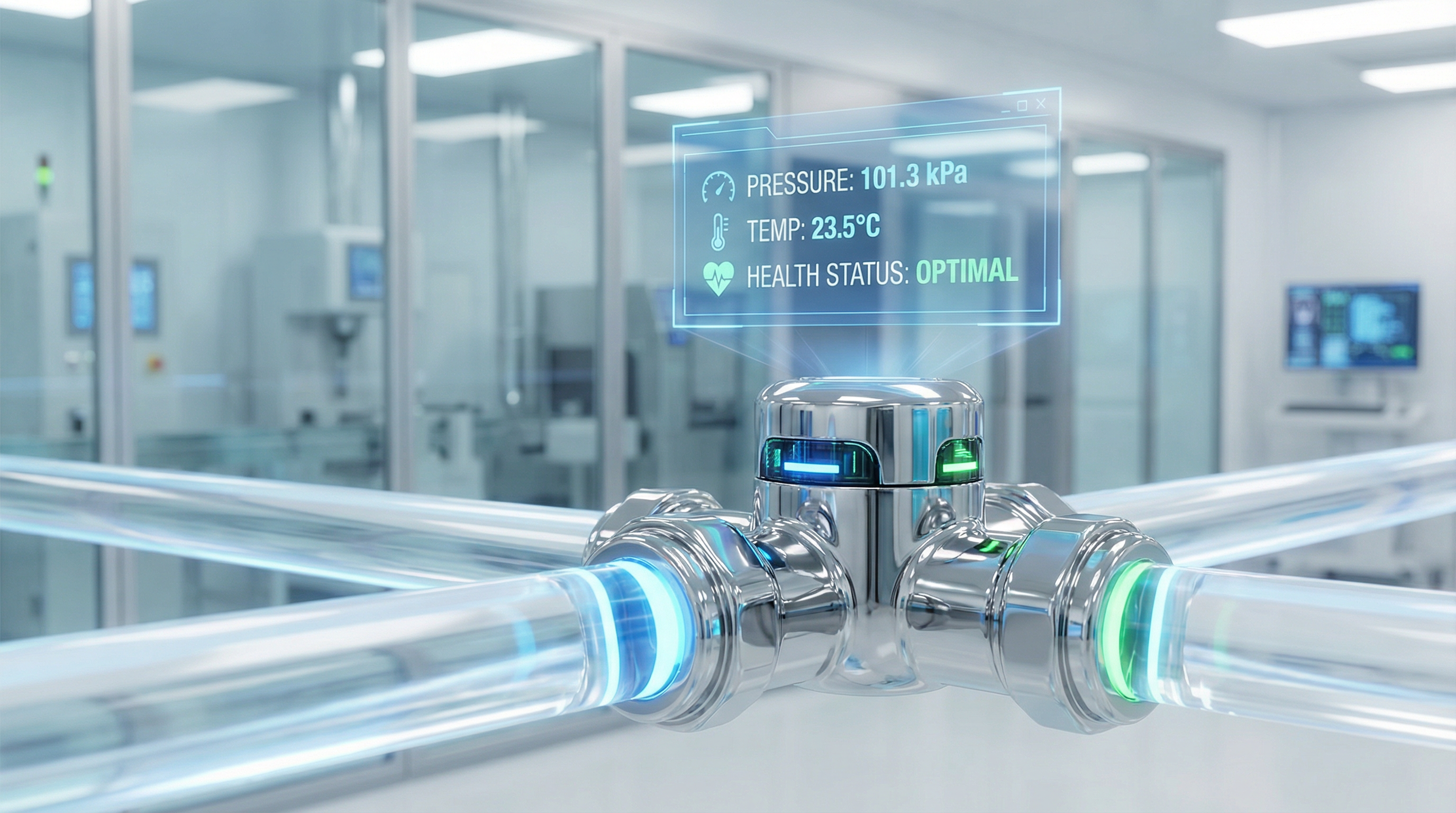
The future lies at the intersection of material science and digital intelligence:
Smart Diagnostics: Embedded sensors feeding ML algorithms to calculate seal RUL.
Advanced Materials: Graphene composites (1000°C limits), Shape Memory Alloys, and Ferrofluidic Sealing for true zero leakage.
Green Manufacturing: Laser cladding repair and 3D printing to reduce carbon footprint.
Conclusion
Valve leakage is a symptom of systemic inefficiency. The transition from passive maintenance to active prevention is reshaping the industrial landscape. For modern enterprises, the goal is clear: Establish a full lifecycle management system that suppresses leakage rates below 0.001%.


