In the complex circulatory system of modern industrial production and daily maintenance, fluid and gas pipelines act as the essential arteries. At the critical junctures of these arteries lie stainless steel and carbon steel quick couplers. Renowned for their rapid connection capabilities, uncompromising sealing reliability, and exceptional corrosion resistance, these components are ubiquitous in hydraulic, pneumatic, and lubricating fluid transfer systems. However, a high-quality component is only as good as its installation. Correctly installing a quick coupler is not merely a procedural formality; it is the definitive factor that ensures the safe, stable operation of the entire system. A flawless installation extends the lifespan of the coupler, minimizes downtime, and drastically reduces long-term maintenance costs.
I. Pre-Installation Preparation
Before any physical assembly begins, meticulous preparation is required. A rushed installation is the primary cause of premature system failure.
Verify Coupler Models and Specifications: Before installation, rigorously cross-reference the coupler's model and specifications with the system's engineering requirements. Inspect the hardware meticulously under good lighting for micro-cracks, thread deformities, or missing gaskets.
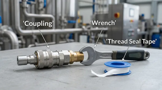
Assemble the Standardized Toolkit: Professional installation demands professional tools, including precision screwdrivers, adjustable wrenches, circlip pliers, PTFE (Teflon) thread seal tape, coolant/anti-seize compound, and a non-negotiable Torque Wrench for thread-based connections.
Audit the Working Environment: Ensure the immediate vicinity is clean and dry. For electrical or pressurized piping systems, absolute isolation is mandatory. Verify that power is locked out and fluid lines are depressurized and drained. Assess ambient humidity and corrosiveness.
Surface Decontamination: Use industrial-grade lint-free cloths and appropriate solvents to eradicate grease, particulate debris, and residual adhesives from the installation interface. Any burrs or deep scratches must be ground down or repaired.
II. Standardized Installation Protocols: Step-by-Step
Step 1: Applying PTFE Tape (For Threaded Connections)
For models relying on threaded connections, always wrap the PTFE tape in the opposite direction of the thread's rotation (typically clockwise when facing the male thread) to ensure the tape is compressed tighter into the grooves.
Step 2: Initial Hand-Tightening
Align the coupler perfectly parallel to the installation port or pipeline. Gently rotate and push until the threads or locking mechanisms engage. Proceed to hand-tighten or use a standard wrench for the initial bite. Do not apply brute force at this stage.
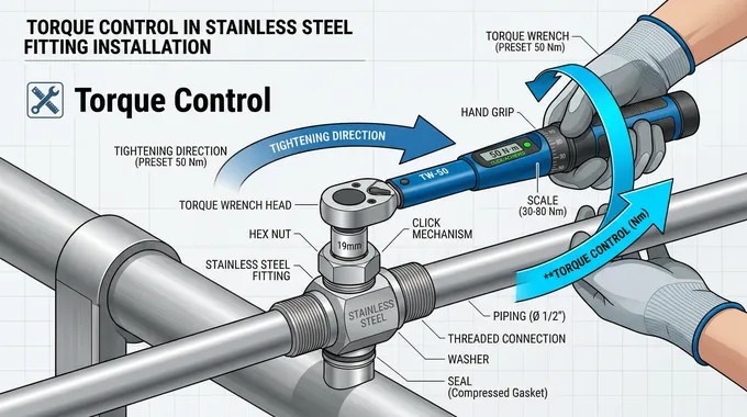
Step 3: Precision Torque Application
For threaded couplers, deploy a calibrated torque wrench. Consult the manufacturer's technical data sheet for the exact Newton-meter (Nm) torque rating specific to the coupler's size and material. Overtightening distorts internal geometries, while under-tightening leads to vibration-induced loosening.
Step 4: Mechanical Verification
Once tightened, physically verify the connection. Apply gentle lateral force to check for microscopic play in threaded joints. For camlock-style couplers, visually and tactilely confirm that the locking arms are fully seated.
Step 5: Strategic Application of Coolant (Optional)
In extreme thermal environments, applying a specialized coolant or anti-seize compound to the joint can mitigate thermal shock and differential expansion between dissimilar metals.
Step 6: Data Logging and Marking
Upon successful installation, use an industrial marker to log the installation date, torque applied, and technician initials directly on the pipe or in the facility's CMMS.
III. Typology-Specific Installation Tactics
Type A (Male Adapter / Female Thread)
Ensure the precise dimensional synergy between the male adapter arc and the female receptacle. Misalignment leads to rapid O-ring degradation.
Apply PTFE tape precisely to the internal threads and use a torque wrench.
Conduct a post-installation pressure test to guarantee absolute hermetic sealing.
Type B (Female Coupler / Male Thread)
The cam arms (levers) must perfectly slot into the groove of the corresponding male adapter. Forceful locking indicates a sizing mismatch.
The male threads require meticulous tape wrapping and torque control.
Post-installation, toggle the cam arms to ensure they operate smoothly without binding or excessive looseness.
Type C (Female Coupler / Hose Shank)
Hose Preparation: The hose end must be cut at a perfect 90-degree angle. Jagged or angled cuts create inherent leak paths.
Insert the shank fully into the hose until it bottoms out. Secure it using heavy-duty hose clamps or crimped ferrules.
Balance the clamping force: too loose causes blow-offs; too tight severs the inner lining of the hose.
Type D (Female Coupler / Female Thread)
This dual-function piece requires sealing on two fronts. Torque the internal threads accurately.
On the quick-connect side, ensure the cam arms securely lock the male adapter, preventing accidental decoupling under hydraulic shock.
Type E (Male Adapter / Hose Shank)
Ensure the male adapter mates flawlessly with the female coupler.
Treat the hose shank connection with the exact rigorous standards outlined for Type C, ensuring deep insertion and balanced clamping.
IV. Critical Operational Precautions
Respect Maximum Pressure Thresholds: Never exceed the specified maximum working pressure (MWP). Pressure spikes (water hammer) can cause catastrophic blowouts.
Thermal Boundaries: Sealing gaskets have strict temperature limits. Operating outside these parameters causes the elastomer to harden, crack, or melt.
Prohibit Mechanical Abuse: Do not use couplers as structural support. Striking, bending, or applying lateral tensile stress will warp the housing and destroy the seal.
Environmental Contamination: Do not operate standard couplers in environments saturated with abrasive metal dust or sand without protective shielding.
Never Exceed Maximum Torque: More is not better. Over-torquing permanently damages thread integrity.
Hose Integrity: Never attach a coupler to a fatigued, cracked, or hardened hose.
Vibration Mitigation: Utilize shock-absorbing flexible hoses to isolate the coupler on vibrating machinery.
Fluid Filtration: The medium flowing through the coupler must be filtered. Abrasive particulates act as sandpaper against internal seals.
Avoid Unnecessary Disassembly: Frequent, unnecessary coupling and decoupling accelerate wear on the locking mechanisms and seals.
V. Diagnostics, Troubleshooting, and Maintenance
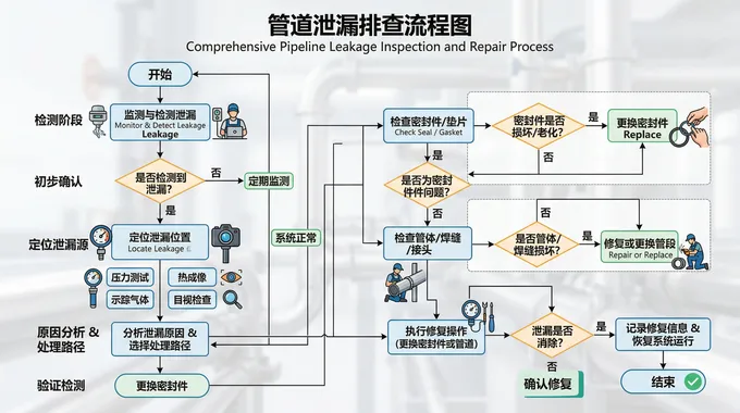
Diagnostics and Troubleshooting
When systems fail, rapid diagnosis is imperative. Fluid Leakage is the most common symptom, often caused by insufficient torque, degraded O-rings, or scored mating surfaces. Solution: Depressurize, dismantle, inspect the O-ring, re-cut the tape, and re-torque. Loose Connections/Vibration Back-off are caused by unmatched thread standards, dirty threads, or failure to engage locking pins. Solution: Replace mismatched parts and clean interfaces thoroughly. Structural Damage is typically caused by water hammer or blunt force trauma. Solution: Immediate replacement and implement pressure-relief valves.
Lifecycle Maintenance and Care
True industrial efficiency is achieved through proactive maintenance. Implement Routine Audits for weeping fluids and external corrosion at least quarterly. Ensure Internal Sanitization through periodic flushing to extend the life of the coupler's internal geometry. Apply Strategic Lubrication to couplers with bearing-assisted swivels or intricate cam mechanisms at specified intervals. Finally, enact Anti-Corrosion Protocols; apply industrial anti-rust coatings or utilize galvanic protection strategies for carbon steel in saline or highly humid environments.
Conclusion: The installation of stainless and carbon steel quick couplers requires a blend of rigorous theoretical understanding and precise physical execution. By adhering to scientifically backed, standardized protocols, maintenance professionals can ensure zero-leak operations, elevate workplace safety, and maximize the return on investment for industrial infrastructure.


