
As the absolute core component of modern fluid control systems, stainless steel pressure regulators are widely applied in critical industries such as petrochemicals, power generation, water treatment, and semiconductor manufacturing. Their fundamental function is to stably reduce high-pressure fluid to a desired low-pressure level, achieving dynamic equilibrium through precise internal components like diaphragms and springs. However, in actual operation, the issue of unstable pressure output occurs frequently. Minor fluctuations can compromise process accuracy, while severe instability may lead to equipment damage or even catastrophic safety incidents. This article provides a systematic and in-depth exploration from four dimensions: structural principles, fault phenomena, root cause analysis, and comprehensive solutions, aiming to offer actionable insights for industry professionals.
I. Working Principle and Structural Characteristics of Stainless Steel Pressure Regulators
The operational logic of a stainless steel pressure regulator is fundamentally based on Bernoulli's principle of fluid mechanics and the law of conservation of energy. It achieves pressure stability through a delicate balance of throttling, depressurization, and feedback regulation. The typical structural configuration includes:
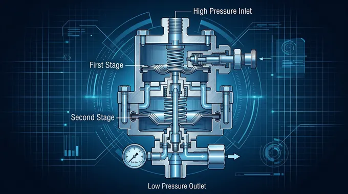
Single-Stage (Primary) Pressure Reduction Valve: When high-pressure fluid passes through the narrow flow channel formed by the valve core and the valve seat, the flow velocity increases significantly. This causes the static pressure energy to convert into kinetic energy, thereby accomplishing the preliminary pressure reduction.
Two-Stage (Secondary) Pressure Reduction Valve: The intermediate-pressure fluid is guided through a flow-directing structure where a portion of the kinetic energy is converted back into pressure energy. The diaphragm senses the change in outlet pressure and immediately transmits a physical signal to the main valve core, realizing precise and dynamic regulation.
Critical Components: The utilization of 316L stainless steel diaphragms, Stellite alloy hard-faced valve cores and seats, high-precision adjustment springs, and multi-stage throttling designs ensures exceptional corrosion resistance and mechanical wear resistance.
Technical Benchmark: Take the German GCE FMD 502 series dual-stage pressure regulator as a prime example. By connecting two independent pressure reduction valves in series, it can stably reduce inlet gas pressures of up to 230 bar down to a precise 0.2-10.5 bar. The pressure fluctuation range is strictly controlled within ±0.1%, fully demonstrating the overwhelming superiority of the dual-stage design in high-demand applications.

II. Typical Fault Phenomena of Unstable Pressure Output
1. Static Pressure Fluctuation: Under no-load conditions (zero flow), the pressure gauge pointer exhibits continuous jittering or trembling, with fluctuation amplitudes reaching ±5% or more.
2. Dynamic Pressure Decay (Droop): Upon activating the load, the outlet pressure drops sharply. The greater the flow rate, the more significant the pressure decay, indicating an inability to maintain downstream supply.
3. Uncontrolled Pressure Creep: After closing the load, the outlet pressure continues to rise abnormally. In severe cases, this phenomenon can trigger the safety relief valve to pop open, posing severe safety risks.
4. Howling and Acoustic Resonance: Under high-flow operating conditions, the regulator may produce high-frequency noise or howling, accompanied by abnormal, destructive vibration of the diaphragm assembly.
5. Abnormal Pressure Gauge Indication: The gauge pointer may stagnate, swing in reverse, or behave erratically, often exacerbated by improper range selection which leads to operational misjudgment.
III. In-depth Root Cause Analysis and Technical Resolution
The instability of pressure output is rarely a single-point failure; it is usually the result of interacting factors.
(A) Structural Parameter Design Flaws
Limitations of Single-Stage Reduction: Single-stage regulators rely on a solitary throttling element. When the inlet pressure fluctuation exceeds ±10%, the stability of the outlet pressure drops significantly. A dual-stage design disperses the pressure differential, effectively mitigating the impact of inlet pressure fluctuations by over 80%.
Insufficient Effective Diaphragm Area: When the effective pressure-bearing area of the diaphragm does not match the stiffness of the regulating spring, pressure feedback is delayed, causing regulation hysteresis. A documented case from a semiconductor enterprise revealed that increasing the diaphragm area from 50mm² to 80mm² reduced the pressure fluctuation amplitude from ±3% to an impressive ±0.5%.
Blockage of the Damping Hole: The diameter of a damping hole is typically tiny (0.3-0.5mm). The intrusion of impurities can distort the dynamic response. Experimental data proves that a blocked damping hole can prolong the pressure adjustment time by 3 to 5 times.
(B) Sudden Changes in Operating Conditions
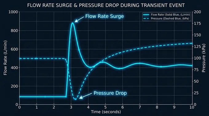
Flow Surges and Shocks: When the load flow suddenly surges to 150% of the rated value, the regulator's outlet pressure can momentarily plummet by 20%-30%. In a chemical plant's reactor case, sudden flow variations caused fatigue fracture of the diaphragm, directly triggering a hazardous fluid leak.
Changes in Medium Physical Properties: For every 10℃ increase in gas temperature, the pressure fluctuation amplitude increases by approximately 1.5%. Furthermore, for media containing abrasive particles, the wear rate of the valve core can be 3 to 5 times higher than that with clean, high-purity media.
Installation Vibration: When the pipeline's vibration frequency aligns with the natural frequency of the diaphragm, resonance occurs, drastically amplifying pressure fluctuations. Simulation experiments indicate that when vibration acceleration exceeds 0.5g, pressure stability decreases by up to 40%.
(C) Deficiencies in Maintenance and Management
Impurity Intrusion: Statistics from a new energy enterprise show that 60% of regulator failures are caused by impurities. A mere 0.1mm particle can cause the valve core to jam, while a 0.5mm particle can severely scratch or puncture the diaphragm.
Diaphragm Aging and Degradation: Nitrile rubber diaphragms in chlorine-containing environments have their lifespan shortened to just 6 months, whereas fluorine rubber (Viton) diaphragms can last over 3 years. A pharmaceutical company suffered direct losses exceeding one million RMB due to high-purity gas contamination caused by an aging, ruptured diaphragm.
Spring Fatigue: After 100,000 operational cycles, the stiffness of a regulating spring can decay by 15%-20%. In a power plant incident, spring failure led to total pressure loss of control, ultimately triggering the boiler's safety relief valve.
IV. Systematic Solutions and Implementation Paths
To completely eradicate pressure instability, a multi-faceted approach combining structural upgrades, intelligent control, and rigorous maintenance must be adopted.
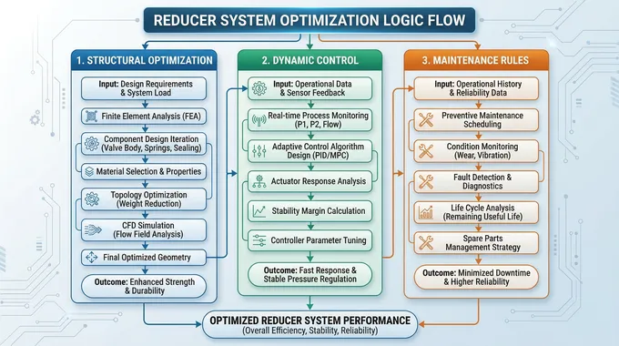
(A) Structural Optimization Strategies
Mandatory Dual-Stage Pressure Reduction Systems: Under conditions where inlet pressure fluctuation is >±10% or flow rate is >500m³/h, dual-stage pressure regulators must be mandatorily deployed. After upgrading, a petrochemical enterprise improved pressure stability by 90% and extended the maintenance cycle to 2 years.
Diaphragm Component Upgrades: Replacing traditional rubber diaphragms with metal bellows diaphragms expands the operating temperature range to -196℃ to +350℃, exponentially increasing the service life to over 10 years.
Multi-Stage Throttling Design: By utilizing a three-stage depressurization structure, the single-point pressure differential is tightly controlled within 5MPa, which can increase the lifespan of the valve core by threefold.

(B) Operational Control Strategies
Dynamic Compensation Algorithms: Introducing advanced PID control algorithms allows for real-time adjustments of the valve core opening. A semiconductor manufacturer applied this, successfully shortening the pressure fluctuation cycle from 5 seconds to a mere 0.5 seconds.
Buffer Tank Configuration: Installing a buffer tank downstream of the regulator is highly effective. The volume is calculated using the formula V = Q × Δt / ΔP (where Q is flow rate, Δt is adjustment time, and ΔP is allowable pressure fluctuation). A food processing enterprise configured a buffer tank and reduced the pressure fluctuation amplitude by 75%.
Intelligent Monitoring Systems: Deploying high-precision pressure sensors and vibration monitoring modules enables automatic alarms when pressure fluctuations exceed ±2% or vibration exceeds 0.3g. Practices in a new energy enterprise demonstrated a fault prediction accuracy rate of 92%.
(C) Maintenance and Management Protocols
Three-Stage Filtration Systems: Installing 10μm, 5μm, and 1μm three-stage filters at the inlet of the pressure regulator and regularly replacing filter elements is crucial. Following this protocol, a pharmaceutical company saw an 85% drop in impurity-induced failure rates.
Diaphragm Lifecycle Management: Establishing usage dossiers for diaphragms and enforcing mandatory replacement when the cumulative operating time reaches 80% of the design life. Statistics from a power enterprise prove that such preventative replacement reduces unplanned downtime by 90%.
Spring Stiffness Testing: Using a spring tester every 5,000 hours to check stiffness. If the deviation is >10%, immediate replacement is required. A chemical enterprise's case study showed that timely spring replacement improved pressure control accuracy by 30%.
V. Industry Application Cases and Data Support
The efficacy of these solutions is backed by substantial empirical data across various high-tech sectors:
Semiconductor Industry: After a 12-inch wafer fab adopted dual-stage pressure regulators, the pressure fluctuation of the specialty gas delivery system plummeted from ±0.5% to ±0.05%, directly boosting the final product yield by 1.2%.
Medical and Healthcare Field: A hospital upgraded its central oxygen supply system to stainless steel dual-stage regulators. Consequently, the frequency of ventilator pressure alarms dropped dramatically from 3 times a week to just once a month.
New Energy Sector: A lithium battery electrolyte production line applied an intelligent monitoring system, which successfully reduced the battery capacity degradation rate caused by pressure fluctuations by 40%.
VI. Technological Trends and Future Outlook
Driven by Industry 4.0 and smart manufacturing, stainless steel pressure regulators are rapidly evolving toward intelligence and seamless integration:
Digital Twin Technology: By establishing highly accurate digital models of pressure regulators, engineers can achieve virtual commissioning, stress testing, and highly accurate fault prediction before physical implementation.
Wireless Monitoring Systems: Leveraging LoRa or NB-IoT communication technologies enables remote, real-time pressure monitoring and cloud-based big data analysis.
Adaptive Regulation Algorithms: Based on advanced machine learning, the system can automatically optimize PID parameters to flawlessly adapt to dynamic and unpredictable operating conditions.
The issue of unstable pressure output in stainless steel pressure regulators is fundamentally the result of the complex interaction among structural design, operating conditions, and maintenance practices. Through systematic solutions—encompassing dual-stage reduction designs, intelligent control algorithms, and preventative maintenance—pressure fluctuations can be strictly controlled within ±0.1%, fully satisfying the rigorous demands of high-precision industries. In the near future, with the deep integration of the Internet of Things (IoT) and Artificial Intelligence (AI), stainless steel pressure regulators will successfully leap from passive maintenance to proactive prediction, providing an unprecedentedly reliable guarantee for global industrial fluid control systems.


